JWST - NIRSpec's Design - JWST NIRSpec
NIRSpec and its DesignNIRSpec Design Overview
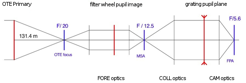
NIRSpec is an all-reflective system with a total of 14 mirrors along with seven interchangeable dispersive elements and eight interchangeable filters. The three major optical sub-systems (FORE, COLL, and CAM) are implemented as three mirror anastigmats (TMAs) that were build, aligned, and verified as stand-alone units in order to simplify instrument alignment. The Figure on the right shows a simplified diagram of the optical path from the optical telescope element (OTE) to the NIRSpec focal plane assembly (FPA). The optical train has three image planes (shown in blue) and three pupil planes (shown in red). The pupil planes are located (i) at the OTE primary mirror, which is the limiting pupil stop of the system, (ii) at the position of the optical filters, and (iii) at the position of the dispersive element (prism or grating). The three image planes of the NIRSpec optical train are located (i) at the OTE focal surface, (ii) the micro-shutter assembly (MSA), and (iii) at the FPA.
The NIRSpec Optical Path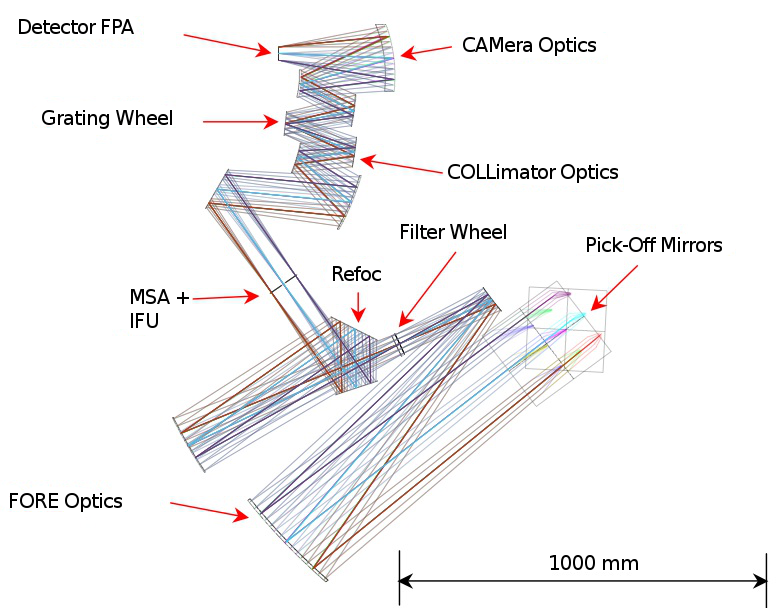 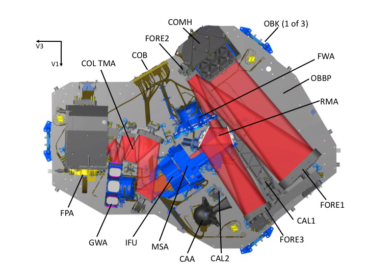 Schematic of the NIRSpec optical train (top) and CAD rendering of the optical bench with the light path denoted in red (bottom).
The first element in the NIRSpec optical path is the Coupling Optics. It consists of two flat mirrors that "pick off" the NIRSpec portion of the OTE focal plane, and redirect the diverging OTE beam (with an f/20 focal ratio) into the NIRSpec fore optics (FORE). A field mask is positioned just in front of the first coupling mirror. The field mask together with a closed optical base plate structure and an internal pupil mask acts to minimize the amount of out-of-field stray light entering the NIRSpec beam.
The FORE optics telecentrically reimage part of the curved OTE focal surface onto the flat MSA aperture plane, creating an accessible pupil image at the filter wheel assembly (FWA). The field of view (FOV) is rotated 41.5° on the sky with respect to most other instruments, in order to take advantage of the natural symmetry axis of the OTE. At the position of the FWA, the beam is nearly collimated (minimizing longitudinal chromatic aberrations), with a nominal incidence angle (of the chief ray) of 5.3º in order to avoid ghosting. The filter wheel itself contains two broadband filters, four long-pass filters, and one clear aperture, all on CaF2 or BK7 substrates, as well an opaque position that serves as an instrument shutter and mirror for the internal calibration assembly (CAA).
The refocus mechanism assembly (RMA) determines the exact position where the telescope focal surface is reimaged onto the MSA. The RMA compensates for any changes in OTE focal position that may occur during launch and throughout the JWST lifetime. Due to the penta-prism geometry of the RMA, adjusting the focus does not affect wave front error (WFE) and does not translate the optical beam laterally.
After passing through the one or more apertures in the MSA plane, the f/12.5 optical beam enters the spectrograph optical system that starts with the collimator optics (COLL). The purpose of the COLL is to transform the divergent f/12.5 beam from the MSA into a highly collimated beam at the grating wheel position. The grating wheel assembly (GWA) contains seven dispersive elements for spectroscopy (a double-pass CaF2 prism and six reflection gratings), and an imaging mirror for target acquisition, flat fielding, and optical distortion calibrations.
After being dispersed or reflected by an optical element in the GWA, the NIRSpec beam enters the camera (CAM), which is the third and final TMA. The CAM focuses the collimated and dispersed beam onto the focal plane assembly. The nominal image scale at the FPA is 5.56 arcsec/mm, so an 18 μm pixel projects to 100 mas on the sky. The focal ratio at the FPA is f/5.6.
The Focal Plane Assembly and SIDECAR ASIC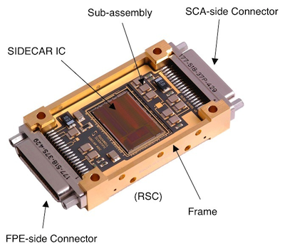 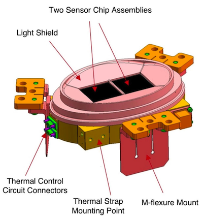 Drawings of the NIRSpec FPA (left) and a SIDECAR ASIC (right).
The NIRSpec FPA contains two closely butted HAWAII-2RG HgCdTe sensor chip arrays (SCAs) manufactured by Teledyne Imaging Systems (TIS). Each SCA has 2048 x 2048 pixels (of which 2040 x 2040 are sensitive to light) that can be addressed individually and read out in a non-destructive way. The light-sensitive portions of the two SCAs are separated by a physical gap of no more than 3.144 mm which – given the mean image scale at the FPA of 5.66"/mm in the dispersion direction – corresponds to 17.8" on the sky.
Because thermal stability is crucial for a good performance of NIR detectors, the FPA is mounted to a thermal strap that connects to a dedicated radiator. In this way, the NIRSpec SCAs can be cold-loaded, and maintained at a stable operating temperature using heaters controlled by a thermal control circuit. The operating temperature will be around 40 K.
The System for Image Digitalization, Enhancement, Control, and Retrieval (SIDECAR) ASIC is used for detector readout and control. It is a special-purpose electronic device individually matched to its corresponding SCA.
The complete detector system is provided by the Goddard Space Flight Center (GSFC) as one of NASA's contributions to the NIRSpec instrument.
Fixed Slits, MSA, and Integral Field Unit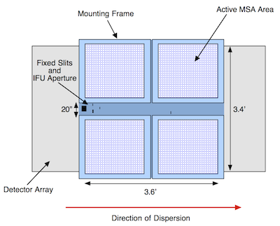 Superimposed sketch of the MSA and FPA image planes.
NIRSpec offers three different kinds of apertures for spectroscopy: several fixed slits for high contrast observations of single objects, and an Integral Field Unit (IFU) for 3D-spectroscopy, and the MSA for obtaining spectra of multiple sources (up to ~100) simultaneously. The MSA is mounted on the NIRSpec Optical Assembly (OA) through a mounting bracket that is also used to mount IFU.
The MSA consists of a 2 × 2 arrangement of quadrants. Each quadrant has 365 shutters along the dispersion axis and 171 shutters along the spatial axis. Pairs of quadrants are separated by approximately 9 mm (22.88") along the dispersion axis and 13.95 mm (36.1") along the spatial axis. The latter gap holds the so-called "cruciform" that provides the permanently open fixed slits and the IFU aperture. Within each quadrant, the shutter pitch is ~0.26" along the dispersion axis and ~0.51" along the spatial axis. The open area of an open shutter is ~0.20" x 0.45". The "walls" separating individual shutters are ~0.06" wide. The MSA is provided by NASA's GSFC as the second contribution to the NIRSpec instrument.
The benefit of the IFU is the ability to obtain the spectrum of a contiguous, extended area on the sky. This is achieved by optically re-arranging all spatial resolution elements within the field of view into a virtual long slit by means of "image-slicing" techniques. The resulting virtual slit can then be dispersed without confusion by neighboring spatial elements. In the case of NIRSpec, a 3" x 3" square field of view (within the ~5" circular window) is dissected into 30 slices of 0.1" width and 3" length each.
The Calibration Assembly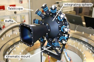 Image of the NIRSpec Calibration Assembly.
The purpose of the calibration assembly (CAA) is to enable on-orbit calibration and monitoring of a number of important instrument parameters such as (i) the geometric distortion between the MSA and the FPA, (ii) the response as a function of both field angle and wavelength, and (iii) the dispersion of the various spectral elements.
Because its light beam does not pass through the NIRSpec filter wheel, the CAA has to provide passband filters that closely mimic the NIRSpec filters. This is achieved by eleven light source assemblies (or "telescopes") feeding light into an integrating sphere. Each telescope contains two lamps for redundancy, dedicated filters for the correct bandpass, and a set of lenses that ensure that the beam from either lamp passes through the filter at the correct angles. Each lamp uses a bulb-enclosed Tungsten filament designed for low power dissipation operation. Due to the integrating sphere design the CAA provides highly uniform illumination.
|
- Removed a total of (5) style text-align:center;
- Removed a total of (5) style font-weight:bold;
- Removed a total of (6) style float:right;
- Removed a total of (1) border attribute.
- Removed a total of (1) cellpadding attribute.
- Removed a total of (1) cellspacing attribute.


 Sign in
 Science & Technology
