RFDU - Ulysses
Telemetry, Tracking, and Command Subsystem
Radio Frequency Distribution Unit
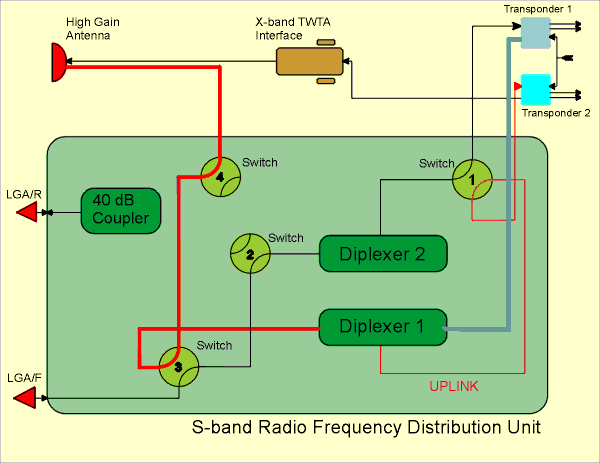
This diagram shows more detail of the spacecraft Radio Frequency Distribution Unit (RFDU). The diagram includes the other relevant units in the TTC subsystem so that you can still see the RFDU's connectivity with other units.
The purpose of the RFDU is to connect the three spacecraft antennae with the two Receivers, and with the two S-band transmitters. This is done using four waveguide switches, so that either receiver and either transmitter can be connected to the High Gain Antenna or either of the Low Gain Antennae. This flexibility is important, because if the operational receiver fails, the redundant one must be connected to the correct input in order for the spacecraft to receive commands from Earth. Similarly either S-band transmitter can be connected to the correct output antenna.
The diagram shows the RFDU in the current operational configuration, which is explained below. For clarity, not all of the waveguide paths are shown - only those relevant to the current configuration. There are many combinations of Receiver, Transmitter, and Antenna made possible by the four waveguide switches, Click here to see examples of other RFDU configurations used earlier in the mission
Uplink
The current uplink path is shown in red. The S-band signal travels via the High Gain Antenna (HGA), through switches 4 and 3, to a diplexer (the diplexer allows two-way radio traffic without interference). The signal is the routed through switch 1 to Receiver 2, currently the prime spacecraft receiver that all telecommands are routed through. If Receiver 2 failed, the switch positions would have to be changed to route the uplink signal to Receiver 1.
S-band Downlink
Ulysses data is transmitted via the X-band downlink, the S-band capability was only used during the early part of the mission when the spacecraft was relatively close to the Earth. However, the S-band transmitter is occasionally used as well, in order to gather Radio Science data. The S-band downlink pathway is shown in grey. The signal travels from Transponder 1, through a diplexer and switches 3 and 4, to the HGA. The S-band transmitter is currently turned off.
Receiver Failure
RFDU switch positions are changed by telecommand. In the current configuration, if Receiver 2 fails, then no further commands can be received by the spacecraft until Receiver 1 is connected to the correct antenna. How can the switch positions be changed to connect Receiver 1 to the LGA/F when no commands can be received via the failed Receiver 2? This is a very serious situation, as potentially the spacecraft could drift without telecommands to maintain it.
To avoid this situation, the spacecraft Data Handling Subsystem (DHS) monitors the receivers and if one should fail, the DHS has the capability to change RFDU switch positions automatically to find a valid uplink path to an operational Receiver. Click here to learn how this is done.


 Sign in
 Science & Technology
