Wire Boom Electronics - Ulysses
Ulysses Upper Equipment Bay
You clicked on the Wire Boom Electronics
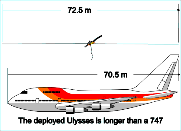
Ulysses has two, 35-metre booms which extend from outboard of the thruster blocks along the +X and -X axes of the spacecraft; these antennae are part of the Unified Radio and Plasma Experiment (URAP). Click here to leave this site and learn more about URAP.
The wire booms could not be deployed until after launch when Ulysses was outside the Shuttle cargo bay and already on its way to Jupiter - because the extended booms would not fit in the Shuttle cargo bay, and because the extended booms are quite fragile and would not survive the high accelerations experienced by Ulysses as its booster rockets started the spacecraft on its journey to Jupiter. The wire booms are two copper-beryllium ribbons 5mm wide and 0.04mm thick, stored rolled on drums before deployment. Control of deployment speed was via a stepper moter and worm drive; there was also a brake to prevent premature deployment of the booms.
The stepper motors are driven by the Wire Boom Electronics (WBE). The WBE receives signals from the spacecraft and conditions them to generate the pulses required to energize the wire boom stepper motors. The Data Handling Subsystem supplies Wire Boom Clock pulses to the WBE, which forwards pulses to the stepper motors. The stepper motors translate the clock pulses into mechanical movements, such that the output shaft rotates a specific angle per pulse. In this way, both booms are deployed with identical speeds - in this case a 128kHz WBC results in a wire boom deployment speed of 10mm/s. This fine control was necessary in order to keep the spin- stabilized spacecraft dynamically balanced in orbit.
The WBE was also used to drive the stepper motor of the axial boom, which is not shown on the spacecraft diagrams but protrudes from the -Z face of the spacecraft.
The WBE is no longer needed since both the wire and axial booms were deployed early in the mission. These booms cannot be retracted.


 Sign in
 Science & Technology
