Detector - XMM-Newton
Detector
The detector is a microchannel plate (MCP)-intensified CCD (MIC). Incoming photons are converted into photoelectrons in an S20 photocathode deposited on the inside of the detector window. The photoelectrons are proximity focused onto a microchannel plate stack, which amplifies the signal by a factor of a million, before the resulting electrons are converted back into photons by a P46 phosphor screen. Light from the phosphor screen is passed through a fiber taper which compensates for the difference in physical size between the microchannel plate stack and the fast-scan CCD used to detect the photons.

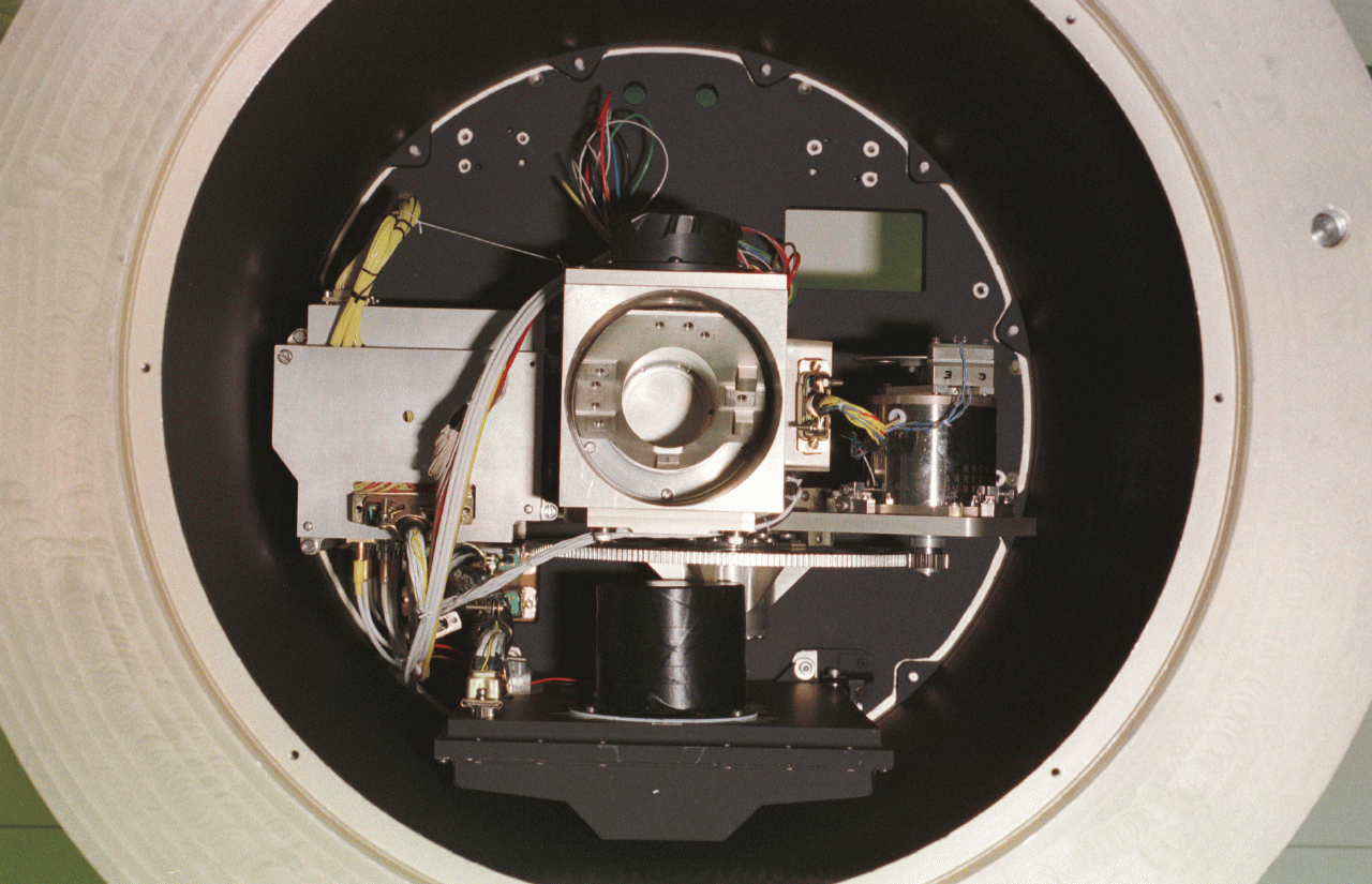
OM telescope with blue detector - front view
Microchannel plates are thin glass sheets made from tiny glass tubes (pores) all of which are aligned in a direction which is almost perpendicular to the sheet. A high electrical potential is applied across the plate which is operated in a vacuum. A photon, ion or electron striking the top of the plate may cause the release of an electron from the inner wall of a MCP pores. This electron is drawn down the tube by the electrical potential until it again strikes the wall where it may liberate further electrons. This process is repeated down the pore until the growing electron cloud reaches the end of the plate and is emitted. For each primary electron entering the tube, more than a thousand may leave it. By using two or three plates in series it is possible to reach gains of up to 100 million. Even 1 million electrons represents a relatively large electrical signal and so MCPs provide a low noise amplification stage in the detection of single photons or sub-atomic particles.
The construction of MCPs is such that an image falling upon one side of a stack of plates is still retained in the distribution of electrons leaving the plate. There are a number of techniques to obtain this image information. In XMM-OM the information is turned back into light by a phosphor screen and collected on a CCD.
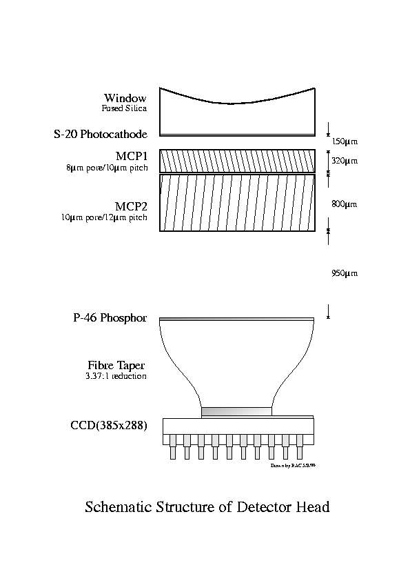
A schematic cut through an OM MIC detector is displayed in the following figure. The light enters from above, passing through an entrance window and hitting a photocathode. From there, the signal is amplified about 100,000 times in total by two consecutive MCPs, before the electrons hit the phosphor layer. The resulting photons are imaged onto the CCD (at the bottom) via a fibre taper which compensates for the different physical size of the MCP stack and the CCD.

Sketch of OM detector
The sensor in the Camera Head (BCH) is an EEV CCD-02-06 which is a frame transfer device running with a vertical clock rate of 1.67 MHz and a horizontal readout rate of 10 MHz. The CCD is of well proven design and is used in many monochrome commercial and scientific TV applications. The dummy output from the CCD is subtracted from the video signal to reduce the level of saturation of the final video amplifier stage. The main cause of this is clock feed-trough in the CCD wiring and the reset spike. The CCD outputs are directly buffered with wide bandwidth emitter followers. The pre-amps are set at a gain of 4, and the differential amplifier at 10, giving a combined gain of 40. Because of the high read out rate, the video signal has settled to only approximately 75% of its final value at the instant of the ADC sample strobe. The gain is therefore slightly higher than that deduced from the CCD manufacturer's published data. The horizontal clock sequencers and ADC sample strobe are derived from a highly stable ECL sequencer circuit based around a twisted ring counter. This, together with a fast horizontal driver circuit design, guarantees minimum timing jitters and hence low systematic noise as required for centroiding the image to 1/8th x 1/8th of a pixel. Under control from the Blue processing Electronics (BPE), the camera is capable of reading out of a number of windows in the CCD image in rapid succession, or full 256 x 256 pixel frames. The integration time is typically 12 ms.
In order that the detector may be calibrated in flight, four flood LED's are provided. They are located off-axis close to the detector. They are positioned so that their focussed emission falls on the side of the filter facing the detector. The filter used would be the blank which then acts as a defocused 'screen' providing the flat field. They are green LED's but with emission in the UV range. Their intensity is controlled via ICB commands routed from the Blue Detector analogue control card to a 4 bit port. There are thus 16 possible levels. They are driven in such a way that if one should fail the remaining LED's will remain fully functional.
Photo courtesy of Mullard Space Science Laboratory, UK.
- Removed a total of (1) style text-align:center;
- Converted a total of (2) center to div.


 Sign in
 Science & Technology