TTC - Ulysses
Telemetry, Tracking, and Command Subsystem
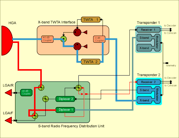
This diagram shows the connectivity between units in the TTC subsystem. Click on an area of this image to obtain a more detailed view of the units of interest.
The X-band downlink path is shown by the blue line running from Transponder 2, to the TWTA Interface Unit and Travelling Wave Tube Amplifier 2 (TWTA2), eventually to the High Gain Antenna (HGA).
The Uplink Path is shown by the red line running from the High Gain Antenna (HGA), through the Radio Frequency Distribution Unit (RFDU), to Transponder 2.
Ulysses occasionally uses an S-band downlink in addition to the prime X-band downlink. This extra signal is used to gather Radio Science data. The S-band downlink is shown by the gray line running from Transponder 1, to the RFDU; from here it follows the uplink path to the HGA. The Transponder 1 S-band output is not used during routine operations.


 Sign in
 Science & Technology
