IoW_20110713 - Gaia
Image of the Week |
Dynamical Attitude Model |
 |
|
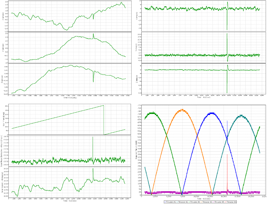
The Dynamical Attitude Model (DAM) is a simulation software developed to achieve a detailed understanding of the Gaia attitude. Its main characteristic is that it takes into account at the same time physical effects and internal hardware components controlling the satellite. This attitude will be used as input for the Gaia data simulations by CU2. By "attitude" we mean the orientation of the satellite and its rotation state. The attitude is characterised by a 7-component array which is recorded for time-step (1 second). This array is composed of:
Currently the model implements the following effects:
All these effects can be modified by means of changing some input parameters, for instance thruster capabilities or micro-meteoroid characteristics. And since the code is very modular, more disturbances could be implemented in the future. The simulation considers the satellite to be a rigid body, for which the motions are described by the Euler equation. It takes about 1 week of computing time to simulate 5 years of spacecraft attitude. These plots show 6h of spacecraft attitude. This simulation includes a micro-meteoroid impact that produces a spike in these plots at about t=15500 seconds.
For more information, please refer to:
This work is being developed by Daniel Risquez and Anthony Brown (both from Leiden Observatory), Floor van Leeuwen (IoA) and Ralf Keil (ZARM). [Published: 13/07/2011] |
- Removed a total of (3) style text-align:center;
- Removed a total of (20) style text-align:justify;
- Removed a total of (1) border attribute.
- Removed a total of (1) cellpadding attribute.
- Removed a total of (1) cellspacing attribute.
Image of the Week Archive
- Removed a total of (1) border attribute.
- Removed a total of (1) cellpadding attribute.
- Removed a total of (1) cellspacing attribute.


 Sign in
 Science & Technology
